Resistor's colour coding
 |
Resistors |
Resistors are small in size, So it is difficult to write on it , to overcome this difficulty radio manufacturers association (RMA) developed the the colour coding system in 1920s and the first colur coded resistor came out in the year1930, in this system colours are used to represent numbers 0-9.
Black 0
Brown 1
Red 2
Orange 3
Yellow 4
Green 5
Blue 6
Violet 7
Grey 8
White 9
You can easily remember the colour codes if you remember the following sentence
"B B R O Y G reat Britain has a V ery Good W ife"
Tolerance
At one end of the resistor there will be a color band, that kept some distance from other bands
Which is the tolerance band. Generally it wil be in golden or silver colour, but other colour band also seen in different resistors depend up on the the resistor's tolerance. Deviation from the nominal value is the tolerance. If golden band is used to indicate tolerance then the resistors tolerance is 5℅ , in the case of silver band it will be 10℅• Very low tolerant resistors also available. For example the tolerance band is brown the tolerance of the resistance value is 1℅ and in the case of violet it wil be 0.1℅.
Three band colour code
See the image of resistor above, can you read the value of the resistor. First colour band is yellow and the second one is orange, then after applying the value we got 43 , now the third colour band that is red then we should add two zeros now it will be 4300 ohm or we can say 4.3 k ( kilo ohm)
Four band colour code
Four band and five band colour codes
 |
Four band and five band colour co
|
See the above image,there you can see both band colour coded resistor and four banded clour coded resistor. Let us try to read the first one, that is brown, black and orange, the value of brown is '1'and the black is '0' so we got 10 , the value of orange that's '3' then we have to put three zeros after 10 then it become 10,000 ohms is equal to 10k.
The next resistor is a four color banded one, here the first three colours that is brown, black, black. That is 100 and final one is red so we adding two zeros the we got the answers 10000 Ohms or 10 k. See the resistance value of both resistors are same, but the colour bands are different.
In the case of five band colour coded resistors apply the the values of first 4 colour bands and put zeros according to the colour value of the 5th band. Six band colour coded resistor is also reading the same way as you read the 5 band clour coded resistor, it has an extra colour band that is temperature coefficient, avoid it.
Reading of smd resistors
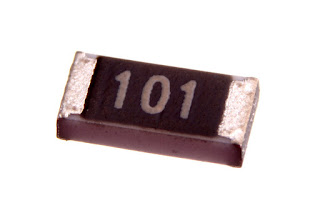
Generally SMD resistors are reading by three band colour code standard , but in the case of precision resistors four digit codes are using. Here you cannot see any colour band, instead digits are printed on it.
Here in the above image there is three digits, 101.First two digits are 10 , the last digit is 1 so we have to add one zero that's 100 Ohms.
Recently another standard is introduced that is
EIA_96. See the image below, can you read it.
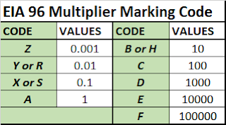
Here the value of the multiplier is C then what to do. See the following tables, the first two digits that's 01 it's value is 100 a the value of multiplier
C =100 so we can put two zeros after 100 then we will get 10000 Ohms is equal to 10K.
 |
| EIA_96 standard marking |
Image credit
Wikimedia
 |
| EIA_96 marking,. Multiplier |
Image credit
Wikimedia


Comments
Post a Comment